


Peugeot 205 Manual
Camshaft and rocker arms - removal, inspection and refittingTU series engine in-car repair procedures / Camshaft and rocker arms - removal, inspection and refitting
General information
1 The rocker arm assembly is secured to the
top of the cylinder head by the cylinder head
bolts. Although in theory it is possible to undo
the head bolts and remove the rocker arm
assembly without removing the head, in
practice, this is not recommended. Once the
bolts have been removed, the head gasket will
be disturbed, and the gasket will almost
certainly leak or blow after refitting. For this
reason, removal of the rocker arm assembly
cannot be done without removing the cylinder
head and renewing the head gasket.
2 The camshaft is slid out of the right-hand end of the cylinder head, and it therefore cannot be removed without first removing the cylinder head, due to a lack of clearance.
Removal
Rocker arm assembly
3 Remove the cylinder head as described in
Section 11.
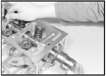
4 To dismantle the rocker arm assembly, carefully prise off the circlip from the righthand end of the rocker shaft; retain the rocker pedestal, to prevent it being sprung off the end of the shaft. Slide the various components off the end of the shaft, keeping all components in their correct fitted order (see illustration).
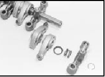
10.4 Remove the circlip, and slide the components off the end of the rocker
shaft
Make a note of each
component’s correct fitted position and
orientation as it is removed, to ensure it is
fitted correctly on reassembly.
5 To separate the left-hand pedestal and shaft, first unscrew the cylinder head cover retaining stud from the top of the pedestal; this can be achieved using a stud extractor, or two nuts locked together. With the stud removed, unscrew the grub screw from the top of the pedestal, and withdraw the rocker shaft (see illustrations).
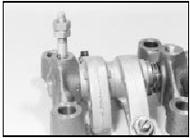
10.5a To remove the left-hand pedestal, lock two nuts together and unscrew
the stud . . .
10.5b . . . then remove the grub screw
Camshaft
6 Remove the cylinder head as described in
Section 11.
7 With the head on a bench, remove the locking pin, then remove the camshaft sprocket as described in paragraphs 6 and 7 of Section 8.
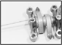
8 Unbolt the housing from the left-hand end of the cylinder head, then undo the retaining bolt, and remove the camshaft thrust fork from the cylinder head (see illustration).
10.8 Undo the retaining bolt and remove the camshaft thrust fork (arrowed) .
. .
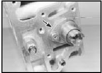
9 Using a large flat-bladed screwdriver, carefully prise the oil seal out of the right-hand end of the cylinder head, then slide out the camshaft (see illustrations).
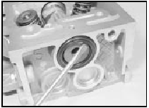
10.9a . . . prise out the oil seal . . .
10.9b . . . and slide out the camshaft
Discard the seal - a new one must be used on refitting.
Inspection
Rocker arm assembly
10 Examine the rocker arm bearing surfaces
which contact the camshaft lobes for wear
ridges and scoring. Renew any rocker arms on
which these conditions are apparent. If a
rocker arm bearing surface is badly scored,
also examine the corresponding lobe on the
camshaft for wear, as it is likely that both will be
worn. Renew worn components as necessary.
The rocker arm assembly can be dismantled as described in paragraphs 4 and 5.
11 Inspect the ends of the (valve clearance) adjusting screws for signs of wear or damage, and renew as required.
12 If the rocker arm assembly has been dismantled, examine the rocker arm and shaft bearing surfaces for wear ridges and scoring.
If there are obvious signs of wear, the relevant rocker arm(s) and/or the shaft must be renewed.
Camshaft
13 Examine the camshaft bearing surfaces
and cam lobes for signs of wear ridges and
scoring. Renew the camshaft if any of these
conditions are apparent. Examine the
condition of the bearing surfaces, both on the
camshaft journals and in the cylinder head. If
the head bearing surfaces are worn
excessively, the cylinder head will need to be
renewed. If the necessary measuring
equipment is available, camshaft bearing
journal wear can be checked by direct
measurement, noting that No 1 journal is at
the transmission end of the head.
14 Examine the thrust fork for signs of wear or scoring, and renew as necessary.
Refitting
Rocker arm assembly
15 If the rocker arm assembly was
dismantled, refit the rocker shaft to the lefthand
pedestal, aligning its locating hole with
the pedestal threaded hole. Refit the grub
screw, and tighten it securely. With the grub
screw in position, refit the cylinder head cover
mounting stud to the pedestal, and tighten it
securely. Apply a smear of clean engine oil to
the shaft, then slide on all removed
components, ensuring each is correctly fitted
in its original position. Once all components
are in position on the shaft, compress the
right-hand pedestal and refit the circlip.
Ensure that the circlip is correctly located in its groove on the shaft.
16 Refit the cylinder head and rocker arm assembly as described in Section 11.
Camshaft
17 Ensure that the cylinder head and
camshaft bearing surfaces are clean, then
liberally oil the camshaft bearings and lobes.
Slide the camshaft back into position in the cylinder head. On carburettor engines, take care that the fuel pump operating lever is not trapped by the camshaft as it is slid into position. To prevent this, remove the fuel pump before refitting the camshaft, then refit it afterwards.
18 Locate the thrust fork with the left-hand end of the camshaft. Refit the fork retaining bolt, tightening it to the specified torque setting.
19 Ensure that the housing and cylinder head mating surfaces are clean and dry, then apply a smear of sealant to the housing mating surface.
Refit the housing to the left-hand end of the head, and securely tighten its retaining bolts.
20 Lubricate the lips of the new seal with clean engine oil, then drive it into position until it seats on its locating shoulder. Use a suitable tubular drift, such as a socket, which bears only on the hard outer edge of the seal.
Take care not to damage the seal lips during fitting. Note that the seal lips should face inwards.
21 Refit the camshaft sprocket as described in paragraphs 17 to 19 of Section 8.
22 Refit the cylinder head as described in Section 11.


